| Home > RX-7 > Tech/Mods > Mods > Megasquirt > Wire The Megasquirt MS3/MS3-Pro Harness Into The Car |
| Home > RX-7 > Tech/Mods > Mods > Megasquirt > Wire The Megasquirt MS3/MS3-Pro Harness Into The Car |
These instructions cover the Megasquirt MS3X and MS3-Pro. If instead you are installing MS1/MS2, then you want to read the MS1/MS2 wiring instructions.
Now the fun stuff can begin when we actually start wiring the Megasquirt harness into the car. This is going to be the most involved section of the writeup and most of the work will take place here. Everything having to do with wiring up the Megasquirt will be covered here including the fuse box, actual Megasquirt wiring, fuel pump and wideband.
As these instructions cover both MS3X and MS3-Pro, there are times when there will be some options in wiring depending on the ECU you are installing. For the most part, the connections are exactly the same except that the MS3-Pro uses more generic terms for some of its I/O. For example, the MS3X "boost" output equivalent on the MS3-Pro is "high current out 3". I will include an MS3X and MS3-Pro wiring diagram and put MS3-Pro equivalents in brackets when referring to MS3X wire names and pin numbers.
You should put some thought into what you might want to do in the future and consider leaving some of these wires in the harness so they are available in the engine bay. For example, if you have a turbo car you will probably want to leave the boost output (MS3-Pro: high current out 3) in the harness because at some point you will probably want to use the boost control feature. Since unused injector outputs can be repurposed as generic on/off outputs, you may wish for example to leave injectors G and H in the harness to control future items (A/C compressor perhaps, or blink the headlights when you go WOT). Don't forget the inputs. SpareADC (MS3-Pro: Analog in 1) can be used with 0 - 5V pressure transducer for measurement of fuel or oil pressure, for example. Or datalog the temperature of the left turn signal if you desire.
I'm presenting a basic installation here to keep things straightforward. If you want to look at some of the features I've just mentioned, take a look at the MS3 hardware manual for info. For MS3-Pro, the manual is available as a PDF download from DIYAutoTune.
For MS3X users from the DB37 end, pull the following wires back:
MS3-Pro users need to pull the following wires back to the connector ends of the harnesses.
What to do with the extra wires is up to you. In most cases I don't recommend cutting them out of the harness because you may want to use them later. As mentioned above, you can run a few of the extra I/O wires to the far end of your harness for future use. The ones left in the car can be coiled out of the way with their ends insulated by about an inch of heat shrink tubing. Then tucked under the ECU bracket or wherever. If you want to get fancy, you could group the unused wire according to function and then install a connector on each group so that you could make sub-harnesses if you decide to use those wires in the future.
Run the harness up along the firewall just above the lip, keeping it behind any emissions plumbing that may still be in place. Run it behind the brake booster and then down under the trailing coil (you will need to remove the coil) and finally all the way along the frame rail until it reaches the battery/leading coil area. Leave enough slack so that harness can follow the contours of its path without being stretched or pinched. There is a lot of harness if you have MS3X so don't worry about running out. MS3-Pro users have a shorter 8 foot harness which requires a bit more care in placement so you don't run out of wire at the far end (leading coil, electric fan).
Now you can start pulling wires from the harness that will be used to connect to the sensor and other components. Pull the Injector A - D (white w/stripe) and thin green Idle (MS3-Pro: PWM Idle Out, green) wires out of the harness around the fuel rail area of the engine. In the same area, also pull the yellow coolant temp (CLT) sensor wire. Run a 12 gauge red wire from the injector area along the harness and fish it back into the car to terminate near the fuse box. Leave plenty of slack. This will provide 12V power to the fuel injectors. To provide a ground for the CLT, run a 16 gauge black wire from the CLT area to the harness along the firewall with a bit of slack. This will eventually tie into the sensor ground wire (black/white). Finally, a 16 gauge red wire needs to be run from inside the car up along the harness and to the BAC valve area. If you have an S4 NA, then the BAC is on the other side of the manifold (mounted to the dynamic chamber) so run those wires while you run the wires to the throttle body.
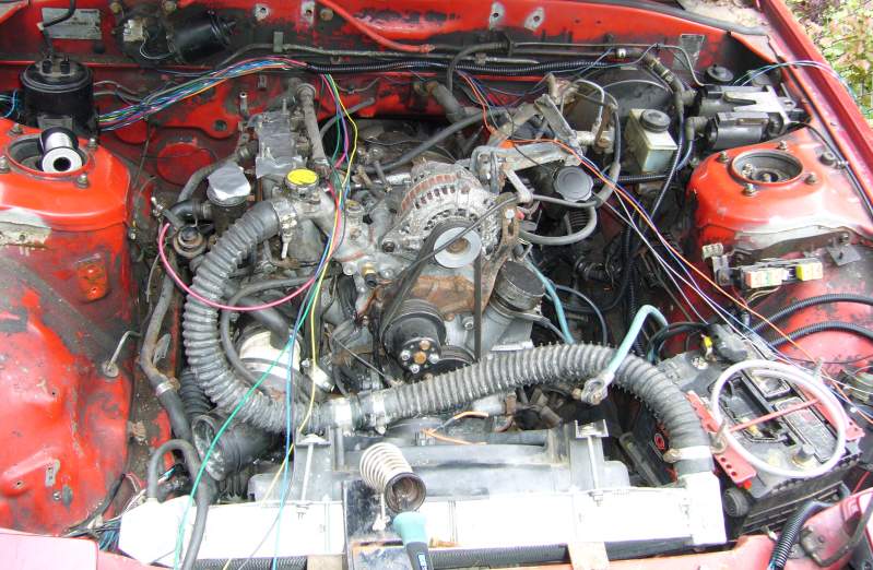
The picture below shows these wires being run on a TII. This is an "in progress" picture so not everything is in place yet. It is also an MS1/MS2 installation, but you get the general idea of what has to happen with the wires even though the colours don't match.
Around the throttle body, you need to run the TPS, CAS and IAT wires. Start by pulling the thin blue (TPS Sensor), gray (5V REF) and orange (IAT) wires to the throttle body area. The two TPS wires will ultimately end up at the TPS (duh) while the IAT wires will end up at the IAT (double duh). Note that S5 NAs have the IAT at the other side of the engine so this wire should be run in the injector area. MS3-Pro users will also need to split the TPS 5V (grey) wire to power the MAP sensor, covered later. The typical location for the MAP sensor is usually somewhere on the firewall around the upper intake manifold, so you MS3-Pro users can just leave the MAP wire (light blue/white) along the firewall. Run the shielded CAS (VR sensor) wires as well to the CAS area. I tend to run all of these wires just past the clutch slave cylinder in one bundle then split them up underneath the intake manifold around the oil filter area. I suggest keeping the CAS wire totally separate though to avoid noise issues. A ground wire for the IAT and TPS is needed so pull the black/white (sensor ground) wire to this area as well. When we actually start soldering, we will split this wire and also tie into it to provide grounds for the CLT, IAT, TPS (and MAP for MS3-Pro) sensors.
The next wires to be run are the coil and e-fan wires. Run Spark A - C (yellow w/stripe) along the driver side of the engine bay, with spark B and C ending up at the trailing coil while spark A ends up at the leading coil. At this point you may want to remove the trailing coil if not already done. From the trailing coil area, run a 16 gauge red wire all the way back to the ECU, leaving slack at each end. We'll use this red wire to provide IGN 12V to the ECU to avoid having to dig under the dash at the ignition switch. The trailing coil receives IGN 12V from the stock main EFI relay.
Feed Injector H (white/purple) out to the front of the car around the driver side front relays (between the bumper and rad). We will be repurposing Injector H to trigger the e-fan relay. From that same relay area, run a 12 gauge red wire all the way back to the ECU. This wire will provide 12V power for the e-fan. Make sure to leave enough slack on both ends of the 12 gauge wire. Additionally, to supply power to the relay coil, run a red 16 gauge wire from the relay area back to the ECU.
We are almost done pulling wires in the engine bay at this point. The final two wires you need to run for the Megasquirt harness are 8 gauge power and ground (red and black) wires from the battery area back to the ECU panel. Leave slack on both ends.
Now, take what remains of your stock EFI harness and reconnect it to the engine. Plug it into the wiper motor, alternator (if applicable) and the dash coolant temp sensor.
Finally, run the O2 sensor wire from the wideband through the wiring grommet to the interior of the car. Position the O2 sensor connector on the inner fender (you will find there are convenient factory holes that the connector will clip to). Remove the stock O2 sensor (plenty of penetrating oil helps here) and then install the wideband sensor with some anti-seize on the threads. Connect the wideband sensor to the connector.
All the rough wiring is now complete in the engine bay so next, we move to the fuel pump wiring inside the car.
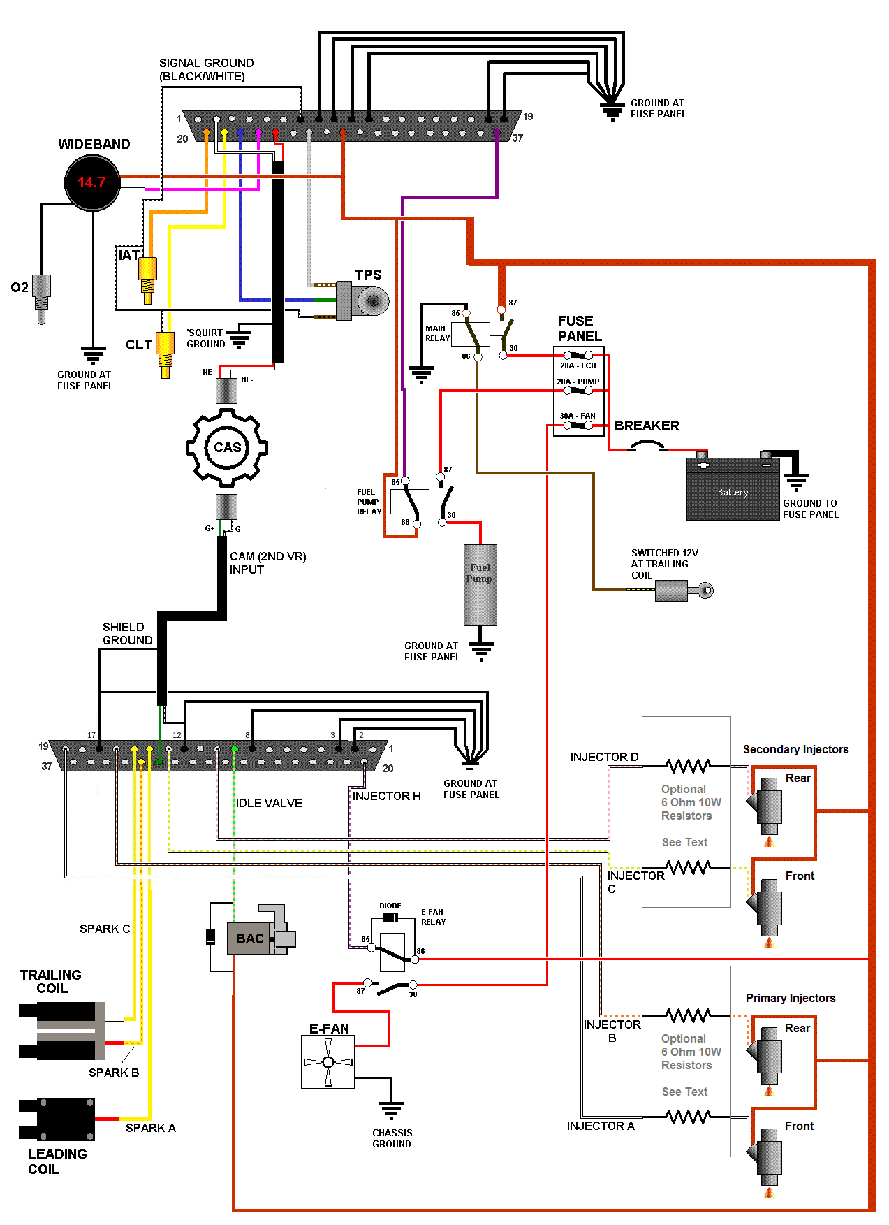
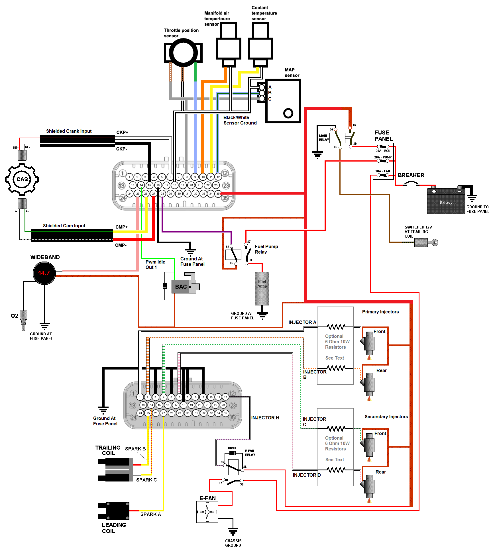
Below are the master wiring schematics for both MS3X and MS3-Pro which show how the system is wired. Obviously you will want to use the schematic which corresponds with your ECU but you can see how similar both are. The only real difference is the addition of the MAP sensor for MS3-Pro, and the pin number changes. All the steps below this will refer back to the schematic so print it out and keep it handy. Anyone who has looked at a Megasquirt wiring schematic before (such as the one in the Megamanual) will be familiar with the basic layout of this schematic. I made these using many of the elements and graphics from the standard Megasquirt schematic. The schematics are a bit huge so what you see here has been resized so it doesn't screw up the formatting on the rest of the page. Click on the image to get a full sized view in a new window.
MS3X Master Schematic
MS3-Pro Master Schematic
The real wiring starts with the engine where the injectors and all the sensors are connected. These instructions will progress from the left to the right of the engine starting with the injectors.
As discussed previously (here and here), injector series resistors will be required if you are running low impedance injectors. If this is the case I suggest you wire them into the harness inside the car so they can be mounted to the ECU panel or to the ECU case. The resistors just need to be wired in series with each injector wire. Pull back enough injector wire into the car so that you can position your resistors where you want them. You're working with the white, white/orange, white/lime green, white/pink wires (INJECTOR A - D). Cut each wire, put a bit of heat shrink tubing over both cut ends, strip a little insulation and then solder in a resistor. Resistors are non-polar so it doesn't matter in which direction they are wired. At this point you can simply zip-tie them to the harness if you wish, but a much more sanitary installation is created by mounting them to the ECU case or a little bit of aluminum plate.

Start by wiring the primary injectors. Loosely place two of your new injector connectors on the injectors (no point in locking them in place now since they will have to be removed later) and run the wires around the fuel rail. Each injector will require one 12V power connection and one MegaSquirt injector drive connection. Lay two of the 12V (red) wires and injector wires A and B (white, white/orange) along the primary injectors. Begin with the front primary injector. Trim, strip and connect one 12V wire to one side of the connector, and INJECTOR A (white) to the other side. The injectors are non polar so it isn't important which side of the injector gets which wire. Now repeat for the rear primary injector by connecting it to 12V (red) and INJECTOR B (white/orange). Don't forget to slip your heat shrink over the wires before soldering.
Now wire the secondary injectors the same way as the first. Connect one side of both injectors each to a red 12 gauge wire and insulate with heat shrink tubing. Connect the other side of the connectors to the MegaSquirt, with INJECTOR C (white/light green) connected to the front secondary injector and INJECTOR D (white/pink) to the rear secondary injector. Insulate all connections with heatshrink tubing.
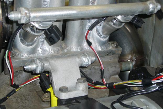
Observant readers will notice that the picture shows a set of not-quite-stock injectors and fuel rails. This car was originally low impedance so a set of RX-8 450CC injectors have been installed in the primary fuel rail (which has been modified with AN fittings). The larger secondaries are not installed and while the intake manifold is custom, their location is the same as in a stock TII configuration. Note the connectors are non-stock to match the injectors. All injector connectors wire the same way: two wires, non polar, one to 12V and one to the MegaSquirt.
Bundle the wires up, securing them in a harness with a few bits of electrical tape. I like to run the bundle between the primary fuel rail and lower intake manifold, splitting each injector connector out at that injector for a neat appearance.
At this point, also splice the black wire from the CLT to the black/white sensor ground wire you ran along the firewall harness earlier. The easiest way to do this is to cut the wire along the firewall closer to the passenger side of the engine and strip both ends. Then trim the wire leading from the CLT appropriately, strip and twist all wires together before soldering. Don't forget to slip your heat shrink onto the correct side of the long black/white wire and NOT the black wire coming from the CLT.
MS3-Pro users require another ground connection for the MAP sensor. If you installing an MS3-Pro, add another ground wire for the MAP sensor to the same splice you made for the CLT sensor. Make this ground wire a few feet long and drape it over near the wiper motor. This means you have 4 wires joined at that point: B/W ground from the MS3-Pro, black for the MAP sensor, black for the CLT, B/W out to the rest of the harness. Be careful how you position your heat shrink as you'll need to slip it over two wires prior to soldering.
There is only one ground wire leading from the Megasquirt harness but two ground connections are needed (TPS and IAT). Split the black/wire (SENSOR GROUND) into 2 wires in the same way that the injector 12V wires were split, making your splice somewhere around the oil filler neck. Insulate it with heat shrink and then run one black wire for the TPS, one for the IAT. You may want to skip placing the upper intake back on until you do this.
If your TPS connector is mangled beyond repair then you will need to replace it with something. If this is the case, most auto parts stores will be able to supply a replacement. Don't ask them for an RX-7 TPS connector, just ask to see a catalog of replacement connectors or bring in the TPS as an example. This writeup presents wire colours based on the stock TPS connector, which you will now need to cut from your old EFI harness. Make sure to leave a few inches of wire so you can make your connections and clean it up with contact cleaner. In addition, the schematic and these instructions reference the wire colours on the harness and not the TPS. This is because harness colours are the same S4 vs. S5, while TPS wire colours are not.
Plug your TPS connector into the TPS so you can trim all the wires to the correct length, then unplug it for soldering. Trim the gray (5V REF), light blue (TPS SIGNAL) and one of the black wires on the Megasquirt harness.
Connect the gray wire from the Megasquirt harness (labelled 5V REF) to the brown/white wire of the TPS connector. Connect the light blue wire from the 'Squirt harness (TPS SIGNAL) to the green wire on the TPS connector. Finally, the black wire connects to the brown/black (S4) or black (S5) wire on the TPS connector.
Yeah, this is not a stock connector so this picture isn't much of a help. But the TII I am using for the majority of these pictures had such a bad connector that I had no choice but to replace it with a WeatherPack unit. If anyone has a good picture of a Megasquirt wired with a stock TPS connector, feel free to email it to me and I'll update this image. This is not an unusual case so you may be facing the same situation. Plus, who is installing a standalone on a stock car anyway? Everyone's install is going to be a little different.
Plug in the IAT sensor connector and then trim all the wires to an appropriate length. The IAT is non-polar so it doesn't matter how you connect it. Connect the orange (labelled IAT) wire from the Megasquirt harness to the sensor connector, and then do the same with the black ground wire you ran. If you are using a DIYAutoTune connector, then it has orange and black wires to match. Almost too easy, eh? Don't forget your heat shrink.
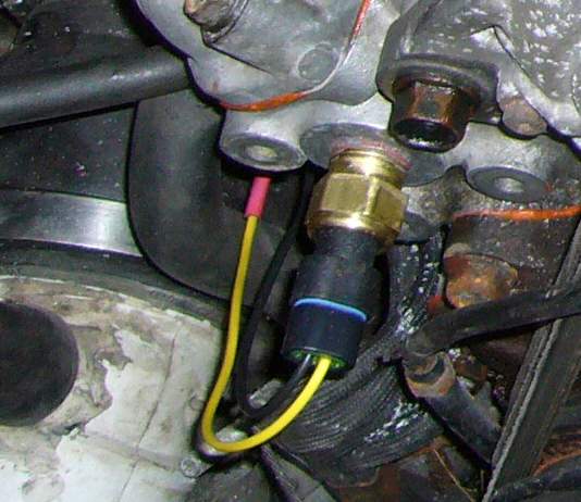
Cut the connector and harness wires to length before slipping a largish diameter piece of heat shrink over the 12V wire and the light green/pink IDLE VALVE wire (MS3-Pro is plain green, PWM Idle Out 1). Then slip some heat shrink tubing over the red 16 gauge 12V wire, and strip about an inch from the end. Now strip an inch from the connector wire. The BAC is non-polar so it doesn't matter which wire you connect. Twist the two wires together and then twist the lead from the banded end of a 1N4001 diode around that joint as per the image below:
Perform the same steps to the light green/pink IDLE VALVE wire (green PWM Idle Out 1 wire for MS3-Pro users), the remaining lead from the BAC connector and the non-banded lead on the diode. This time, make sure to put your heat shrink on the wire from the BAC connector otherwise you will not be able to slip it over the diode.
Solder both connections and then slip the heat shrink over them and shrink it.
Finally, shrink the large piece of tubing over the entire joint to seal it.
At this point you may have noticed that the connector doesn't actually fit the BAC valve. The locating bump of the BAC valve is off center, while the notch in the connector is in the middle. To remedy this, file the bump off of the BAC.
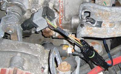
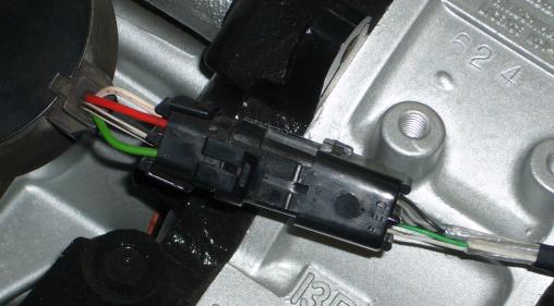
Cut the CAS connector off of the engine harness, making sure to leave a few inches of slack on the cables. Thoroughly clean it with contact cleaner and then examine it for damage. If you find loose pins, cracked insulation or corroded wires, replace it.
Refer to the master wiring schematic when wiring the CAS to make sure everything is correct. The colours of the wires shown in the schematic represent the wires on the CAS itself, not the harness connector. This is because the colours of the harness itself changed between S4 and S5 so to avoid confusion, always go by the wire colours on the CAS.
MS3X CAS Wiring
Remember those notes you took when wiring the shielded cable to the DB37? Well, you need them now because the last engine sensor (and the most important) to be wired is the CAS. It is vitally important you get this wiring correct. While the engine will still run if you reverse the polarity of the sensors, timing will be way off and you'll never be able to set it right. Ignore this, and you will be picking apex seals out of the mufflers.
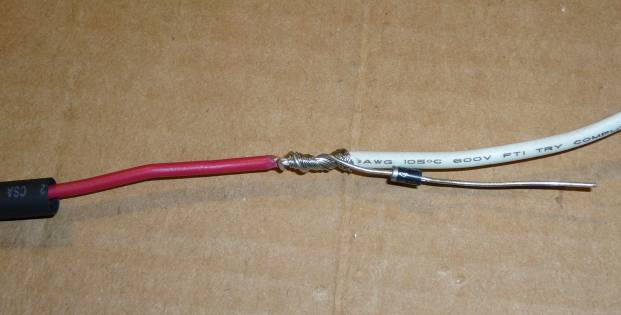
Remember your heat shrink, and try to keep the wires as short as possible. You don't want a lot of unshielded CAS wiring in the engine bay. Before you connect up any of the CAS wires, slip a big piece of heat shrink over the shielded cables. Working with the mainboard harness, connect the wire on the CAS plug corresponding to the red wire on the CAS to the shielded wire on your harness leading to pin 24 of the DB37. Now do the same for the white CAS wire, but connect it to pin 2 of the DB37. Switching over to the shielded wire on the MS3X harness, connect the wire on the CAS plug corresponding to the green wire on the CAS to pin 32 on the DB37. Finally, do the same for the white/black CAS wire and connect it to pin 12 of the DB37. Shrink all your heat shrink and then bundle up the two shielded cables with a bit of electrical tape.
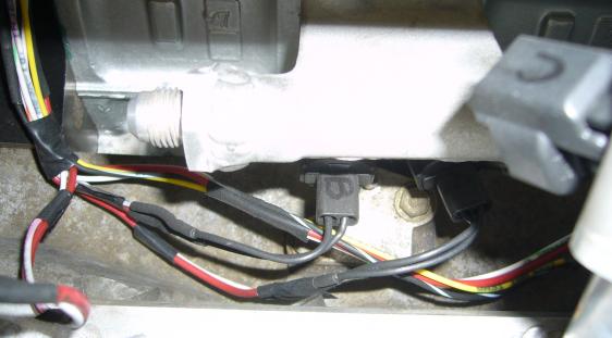
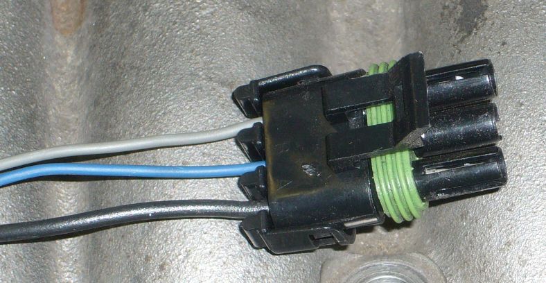
Here is an image of a single shielded cable used with the stock CAS harness:
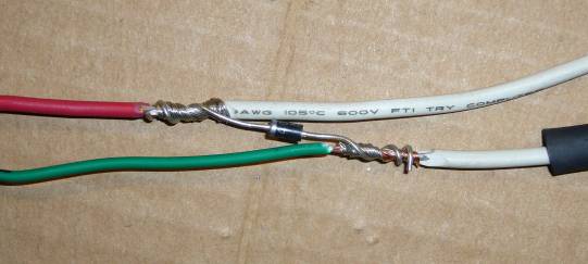
MS3-Pro CAS Wiring
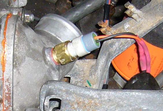
MS3-Pro users have more straightforward CAS wiring since the shielded wires are factory installed in the harness. Start by slipping a big piece of heat shrink over each of the shielded wires. Working with the CRANK (CKP) inputs, connect CKP+ (pin 6, white connector) to the wire on the CAS plug corresponding to the red wire on the CAS. Now do the same for the white wire on the CAS, connecting it to CKP- (pin 15, white connector). Do not forget your heat shrink on those smaller wires as they are quite thin and will need reinforcement. Shrink your large piece of heat shrink over the CRANK (CKP) inputs. Now working with the CAM (CMP) inputs, repeat the same procedure. Connect CMP+ (pin 26, white connector) to the CAS green wire. Then finally, connect CMP- (pin 27, white connector) to the white/black wire on the CAS. Shrink all your heat shrink and then bundle up the two shielded cables with a bit of electrical tape.
Here's an image showing an MS3-Pro using 2 conductor shielded cables where the worn out CAS plug was replaced by a WeatherPack connector:
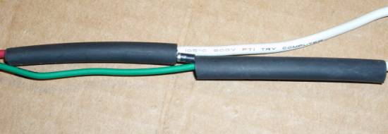
To finish up, seal up all of the CAS wires as appropriate with the big shrink tube. Not only does this keep the weather out but it provides strain relief to the more delicate wires of the shielded cable and CAS connector.
MS3-Pro users have another sensor to wire up, and that's the MAP sensor. In my opinion, the best place for the map sensor is in the little area on the right side where the ECU harness passes into the engine bay. This is the same area in which the sub zero tank, cruise control actuator and charcoal canister live. It's out of the way of engine bay heat for the most part, not too far away from the intake manifold, and near the wiring harness.
The MAP sensor has three connections which are provided by a 3 position WeatherPack connector. The DIYAutoTune MAP sensor connector is pre-wired with pigtails which can be connected to the MS3-Pro harness. First though, we need 5V to power the sensor. Locating the gray 5V TPS REF wire (pin 8, white connector), split it near where the harness enters the engine bay just as you did the ground wire earlier. Cut the wire and strip about 1/2" on each side. Slide some heat shrink over the half leading out to the engine. Now, using some of the extra length you cut off of that wire earlier, strip 1/2" of insulation and twist all three wires together. Solder the joint, clean off flux, and shrink the tube.
Connect the black ground wire (run earlier) to pin A of the WeatherPack connector. Pin B on the WeatherPack connects to the MAP In wire which is light blue/dark blue and connects to pin 12 of the white connector. Finally, connect the 5V TPS REF wire you split to the remaining WeatherPack pin, pin C.
The MAP sensor can be mounted simply by using two self tapping sheet metal screws approximately above where the harness enters the engine bay.
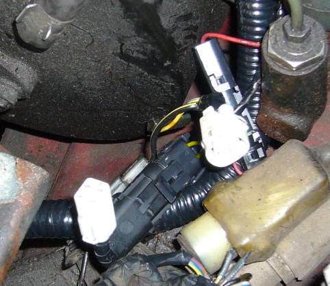
Congratulations! You have just completed the engine wiring section. It wasn't so bad, was it? Next, we need to wire the coils and fan.
As the coils and fan are on the same side of the car, this section of the writeup deals with wiring them. There are far fewer connections here then on the engine but they are just as important. We need to connect the trigger signals to both coils, and IGN 12V lead to switch the main relay and the power/relay arrangement for the fan. We'll start with the trailing coils.
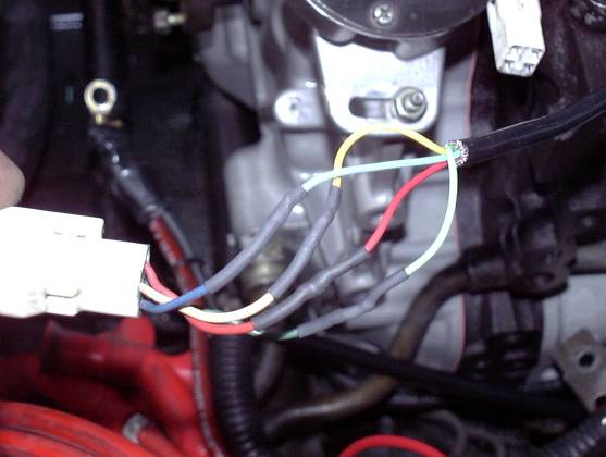
The trailing coil receives power from the front body harness via the two conductor plug which connects to its tan wires. The other connector provides it triggering signals through two of its connections and allows a tach signal back into the harness through the remaining pin (I don't think anyone, including Mazda, knows what the fourth wire is for. If you know, drop me a line...). There are two ways to make the connection to the trailing coil that don't suck; you can cut the connector off the harness and then reconnect the tach wire through a single wire connector, or you can use a 3 (I'll explain the 3rd connection later) pin connector to connect the Megasquirt harness to the body harness. I personally don't like molesting the stock body harness as replacement is not exactly straightforward, so I recommend adding a connector. But it is far easier to cut the connector off of the body harness, wire it to the Megasquirt harness, and then use a single quick connect (spade) terminal for the non-critical tach connection back into the harness.
Regardless of what you choose, you need to make the following connections. Connect the red (trigger) wire on the trailing coil to SPARK B (MS3X: yellow/orange, pin 33 on MS3X DB37, MS3-Pro: yellow/orange, pin 25 on gray connector). Then connect the white (toggle) wire to SPARK C (yellow/light green, pin 29 on MS3X DB37) if you are installing MS3X or SPARK C (yellow/red, pin 14 on gray connector) if you are installing an MS3-Pro.
Also at the trailing (and leading, for the record) coil is a handy source of switched 12V ignition. You will find this signal on the black/yellow wires on the harness side of the two tan-wire connector. Connect up the spare red wire you ran earlier to one of the black/yellow wires.
In the image above, the connections to the front body harness are made using two WeatherPack style connectors, which are available at almost every good auto parts store. A two terminal connector makes the connection to the trailing coil toggle and trigger wires, while a single terminal connector is used for the 12V IGN signal. You can use the connector of your choice but I highly recommend a WeatherPack style connector be used. Most auto parts stores sell them with pigtail leads attached so that you can solder them directly where needed. Molex connectors can be used, but I would recommend staying away from spade (quick connect) connectors unless they are weather tight or you seal them with heat shrink. You'll notice that nowhere I recommend making a soldered connection between the two harnesses. This makes troubleshooting a lot easier and is far more convenient if one of the harnesses has to be removed.
With the wiring done here, you can reinstall the trailing coil.
Connect terminal 87 on the relay to the fans 12V+ connection. Every aftermarket fan tends to use a different style connector so your choice here will depend on the type of connector employed by the fan. Then ground the fans negative connection to a good spot on the chassis using a ring terminal and plenty of dielectric grease. You need to insert a diode between the positive wire to the relay coil and the Megasquirt wire just as you did for the BAC valve. So, connect terminal 85 on the relay to both the non-banded end of a diode, and INJECTOR H (white/purple pin 20 on the MS3X DB37, also white/purple for MS3-Pro but on pin 12 on the gray connector) as described in the BAC instructions. Connect pin 86 of the relay to the banded end of the diode and the 16 gauge red wire (which will supply key switched 12V to the relay coil) you pulled earlier on. Pin 86 on the relay needs 12V to power the fan so connect it to the red 12 gauge 12V wire. Refer to the schematic if those instructions are a bit confusing. Now heat shrink everything up and mount the relay and socket to the chassis of the car.
The final bit of engine bay wiring is to wire the main battery and ground feed to the ECU panel. This feeds the Megasquirt and accessories with a clean source of 12V that is separate from the existing 20 year old wiring in the car. Bringing another 12V feed into the car also has the advantage of providing a convenient place to attach add-on circuits and making troubleshooting easier.
Making these final connections is quite easy. Take the 8 gauge black wire you've already run to the battery area and crimp on a ring terminal. Make sure to use dielectric grease and preferably use a heat-shrinkable type ring terminal. If your terminal is the non-sealed type, use heat shrink to seal up the connection. Now connect this ring terminal to the bolt on the negative battery lug.
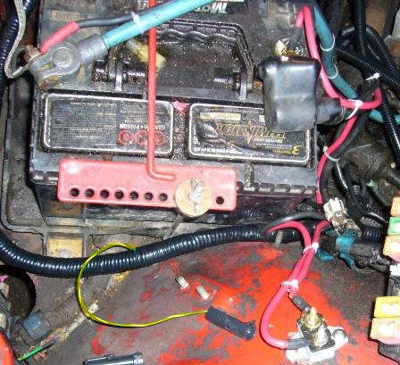
To connect the positive, you must first mount your 40A breaker to the chassis. There is plenty of space on the inner wheel well near the battery but the final location is up to you. Just make sure that it is physically close to the battery. Using ring terminals, make up a section of 8 gauge red wire to connect between the positive lug on the battery and the "battery" terminal of the breaker. Then use another ring terminal to connect the 8 gauge red wire you ran in the Megasquirt harness to the "aux" or "output" terminal of the breaker. The picture above shows both of these connections and how the wires are neatly tied to follow the stock battery cables. For now, leave the positive disconnected at the battery.
The engine bay wiring is now totally complete, so it is the traditional time to sit back with your favourite beverage and contemplate where you might have screwed it up. While you are enjoying your beverage, you may want to take the time to go over each connection and make sure things agree with the schematic. You won't be seeing the engine bay again for a while because now it is time to wire the stuff inside the car.
Back To Mods Page | Mail Me | Search | ![]()