Solid State Tesla Coil Circuit


Home > Circuits > Power Supply > Solid State Tesla Coil
Author Views Views Today Rank Comments
146,839 1 4
Similar to the two transistor solid state Tesla Coil already on this site, this solid state Tesla Coil design uses a normal flyback transformer to generate it's high voltage output. Unlike the other circuit, this one does not use two huge power transistors and high wattage resistors. Instead it uses a 555 timer to more efficiently drive a single MOSFET. It's waveform has adjustable off and on time, making for an efficient circuit with little waste heat. It can be adjusted to drive most commonly found flyback transformers and can operate from a 12V to 18V supply. HV output can reach 60KV or more depending on the transformer and supply voltage.

DANGER: HIGH VOLTAGE DANGER: HIGH VOLTAGE DANGER: HIGH VOLTAGE DANGER: HIGH VOLTAGE DANGER: HIGH VOLTAGE

Schematic

Schematic of the Solid State Tesla Coil

Parts

Part
Total Qty.
Description
Substitutions
R1, R5, R93180 Ohm 1/4W Resistor
R2110K Pot
R3, R7210 Ohm 1/4W Resistor
R415K Pot
R617.5K 1/4W Resistor
R81150 Ohm 1/4W Resistor
R1011 Ohm 5W Resistor
C110.0047uF 50V Polyester Capacitor
C210.05uF 50V Polyester Capacitor
C31220uF 25V Electrolytic Capacitor
C410.01uF 1200V Polyester Capacitor
Q1, Q222N2222 NPN Transistor2N3904
Q31SSM5N55 MOSFET
U11555 Timer Integrated Circuit
U21LM7809 9V Linear Regulator
L11100uH Choke Coil
T11Penn-Tran 1-017-5372 Flyback TransformerSee Notes
MISC1Board, Wire, Case, Socket for U1, Heatsink For Q3, Output Terminal (See Notes)

Notes

  1. T1 as specified in the parts list is going to be almost impossible to find, but don't worry. Penn-Tran was bought by Wiltron and no longer exists. However, most any medium to large flyback transformer will work as long as it does not have an internal rectifier. Suitable units are most often found in TVs made during the 1970s and 1980s. Look for the most impressive, dangerous, menacing transformer you can find. If you need an idea, a picture of a great transformer for use in this circuit:

    Nice flyback tranformer for HV circuit use

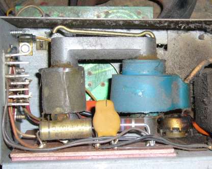
    These can be found in a small metal box generally in the corner of the TV case, complete with a very handy voltage multiplier unit and usually a nice heatsink.

    You will need to either look up the datasheet for the transformer you have, or probe it with an ohmmeter to identify the coil connections. Most flybacks have a load of taps on the HV side to provide focusing, horizontal and vertical signals. These taps are generally of no use to you. To find the primary (coil B-A on the schematic) you need to find the two lowest resistance connections that are not also connected to the HV secondary wiring. Alternately, if your flyback has an open frame like the one in the picture, you can wind on 5 or so turns of 16 gauge magnet wire as a primary. You will need to experiment with the number of turns to get maximum output. The HV ground lead (connection C on the schematic) is generally easy to locate. It will come from the HV secondary and be tied to the frame of the transformer or chassis ground.

    If by some miracle you were able to locate the Penn-Tran transformer, then connection B is the red dot on the transformer, A corresponds to the black dot, and C matches the orange dot.

  2. If the TV you salvaged the transformer from has a voltage multiplier unit (visible slightly at the far right of the above picture), then take it as well. It can multiply the output of this circuit into very high (over 100KV) DC voltages.
  3. When building the circuit, leave the flyback disconnected. Connect a 10 Ohm 10W resistor in place of the primary of T1 and connect a scope to the collector of Q3. Adjust R4 to produce an off time of about 10 microseconds. Adjust R2 for an on time of about 70 microseconds. Now remove the scope, 10 ohm resistor, and connect up T1. Power the circuit back on and you should have a high voltage available at the output. If you do not have a scope, just set both pots in their middle position and then adjust them by trail and error until you get the biggest spark at the output of T1.
  4. Q3 will require a heatsink.
  5. Needless to say, this circuit can produce dangerous voltage. At the very least you are looking at a painful shock. More then likely a decent burn will result from contact with the HV output, as well as instant and uncontrollable muscle contraction. If you have heart problems, don't build this circuit. Be careful!.

Related Circuits

6V to 12V Converter, Portable CD Player Adapter For Car, Car Battery Charger, Automatic 12V Lead Acid Battery Charger, Solid State Tesla Coil/High Voltage Generator, 12VDC To 120VAC Inverter, LASER Power Supply, Power Supply, High Current Power Supply, Dual Polarity Power Supply, High Voltage High Current Power Supply, Transformerless Power Supply, Fixed Voltage Power Supply, Voltage Inverter, Voltage Inverter II, Automatic Load Sensing Power Switch, 12V To 24V DC-DC Converter, Solid State Tesla Coil

Comments

Add A Comment

DEV
24VDC INPUT , SOLID STATE, LOW ENERGY 3 JOULES ,3KV OUTPUT IGNITION CIRCUIT
Friday, June 02, 2017 5:54:40 AM
Sir, I am interested to assemble the subject unit for my experimental turbine engine. Kindly provide me the circuit and I will be be very thank full to you. From .....devassy
anonymous
Solid State Tesla Coil
Sunday, November 30, 2014 8:54:13 AM
This really isn't a Tesla coil. It's just a high voltage flyback power supply. While it should generate high voltages, it is not a tesla coil.
anonymous
Solid State Tesla Coil
Wednesday, May 05, 2010 11:00:59 PM
Can't find a datasheet or substitute for this Mosfet anywhere.
anonymous
Solid State Tesla Coil
Friday, April 09, 2010 5:32:23 PM
is it possible to get t1 from a junked TV?
The last 10 comments are currently shown. Show All Comments. Add A Comment

Back To Circuits Page | Mail Me | Search